BeagleBone Black GPIO Performance: PRU -> 2 memory mapped different GPIOs
In this test we change two different GPIO-banks (0 and 2) from the PRU in order to estimate the maximum performance and check the coherence of the signals.
Some interesting details:
clock cycles per operation
Most operations, such as ADD,SUB,QBxx,MOV,JMP etc.: 1 cycle
LBBO 1,2,4 Bytes from PRU DRAM: 3 cycles
LBBO 8 Bytes from PRU DRAM: 4 cycles
LBBO 12 Bytes from PRU DRAM: 5 cycles
LBBO 16 Bytes from PRU DRAM: 6 cycles
LBCO 4 Bytes from DDR: 43 cycles
LBCO 8 Bytes from DDR: 44 cycles
LBCO 12 Bytes from DDR: 45 cycles
LBCO 16 Bytes from DDR: 46 cycles
GPIO performance
// PRU GPIO Write Timing Details
// The actual write instruction to a GPIO pin using SBBO takes two
// PRU cycles (10 nS). However, the GPIO logic can only update every
// 40 nS (8 PRU cycles). This meas back-to-back writes to GPIO pins
// will eventually stall the PRU, or you can execute 6 PRU instructions
// for ‘free’ when burst writing to the GPIO.
Source Code
.origin 0
.entrypoint TOP
#define GPIO0 0x44e07000
#define GPIO1 0x481ac000
#define GPIO2 0x481ac000
#define GPIO3 0x481ae000
#define GPIO_SETDATAOUT 0x194
#define GPIO_CLEARDATAOUT 0x190
#define DELAY 25 //number regarding to the titles
TOP:
LBCO r0, c4, 4, 4 //load SYSCFG register to r0 (use c4 const addr)
CLR r0, r0, 4 //clear bit 4 (standby init)
SBCO r0, c4, 4, 4 //store the modified r0 back at the load address
//memory assignments
mov r1, GPIO0 | GPIO_SETDATAOUT //load addr for gpio, set data r1
mov r2, GPIO0 | GPIO_CLEARDATAOUT //load addr for gpio to clear data
mov r3, GPIO26 //write 1, 9th bit GPIO73
mov r4, GPIO2 | GPIO_SETDATAOUT
mov r5, GPIO2 | GPIO_CLEARDATAOUT
mov r6, GPIO73
LEDON:
sbbo r3, r1, 0, 4
sbbo r6, r4, 0, 4
mov r0, DELAY //store the length of the delay in REG0
DELAYON:
sub r0, r0, 1 //Decerement REG0 by 1
qbne DELAYON, r0, 0 //loop to delay DELAYON, unless REG0=0
LEDOFF:
sbbo r3, r2, 0, 4
sbbo r6, r5, 0, 4
mov r0, DELAY
DELAYOFF:
sub r0, r0, 1 //decrement REG0 by 1
qbne DELAYOFF, r0, 0 //loop to delayoff unless reg0=0
jmp LEDON
GPIO frequency xx, delay in program 1000, 0,05 µs TIME/DIV


GPIO frequency xx, delay in program 100, 0,1µs and 0,5 µs TIME/DIV


GPIO frequency xx, delay in program 50, 0,1µs and 0,5µs TIME/DIV

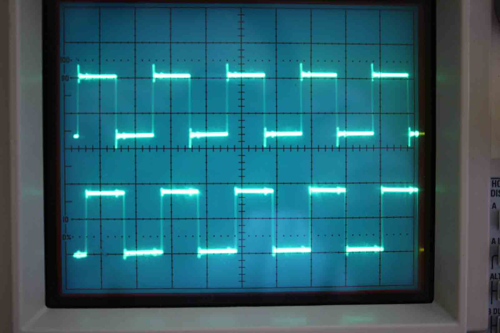
GPIO frequency xx, delay in program 30, 0,1µs TIME/DIV

GPIO frequency xx, delay in program 25, 0,1µs TIME/DIV

GPIO frequency xx, delay in program 20, 0,1µs TIME/DIV

GPIO frequency xx, delay in program 15, 0,1µs TIME/DIV

GPIO frequency xx, delay in program 10, 0,1µs TIME/DIV