Multichannel RTL-SDR
This is a short introduction for getting started in the Linux environment using librtlsdr, MATLAB and GNU Radio. You have to use the RTL-SDR experimental branch from keenerd.
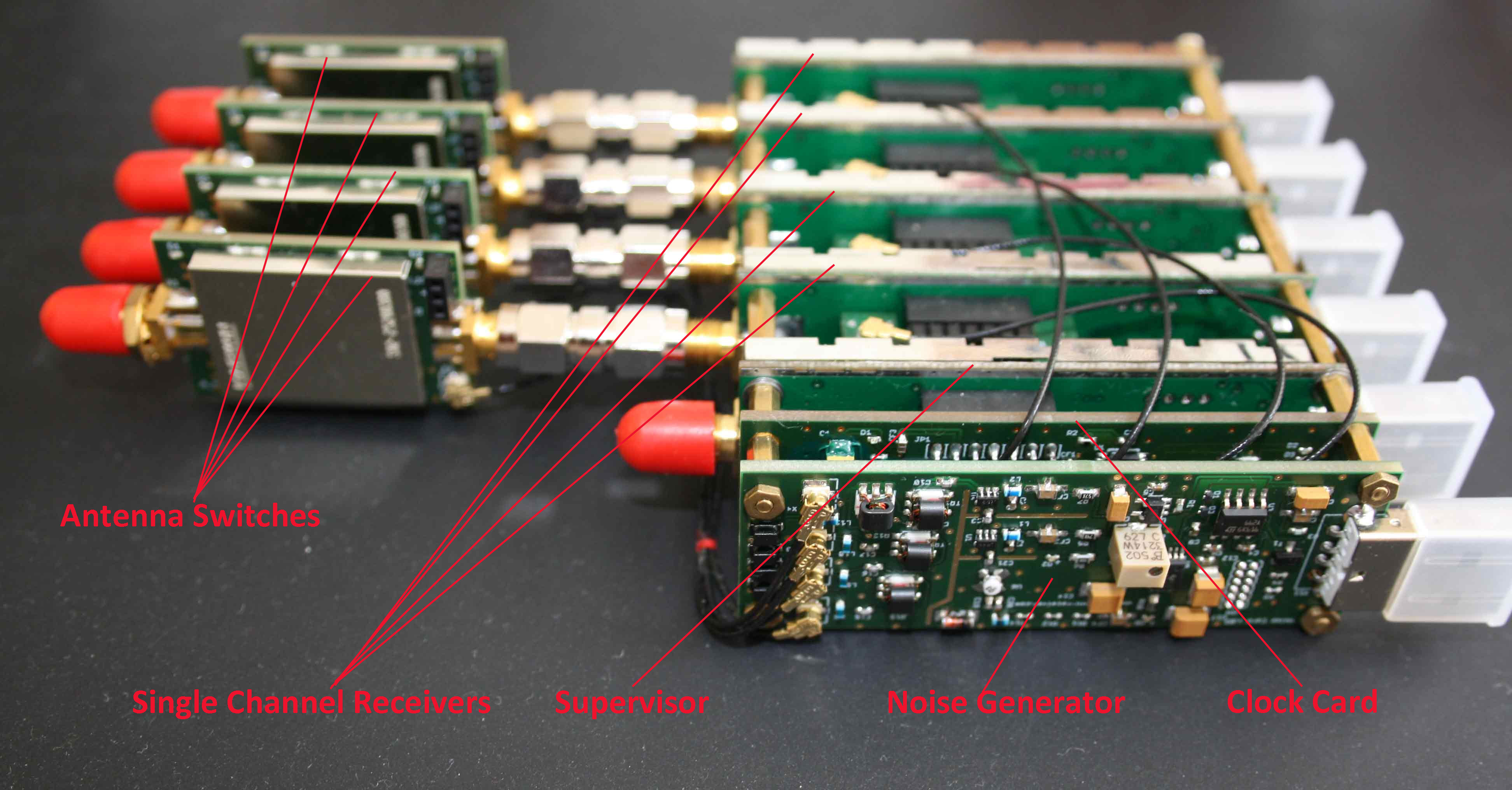
Hardware configuration and checking
Bias Tee activation
The default state of the system is noise but you need to activate the bias tee on the antenna switches.
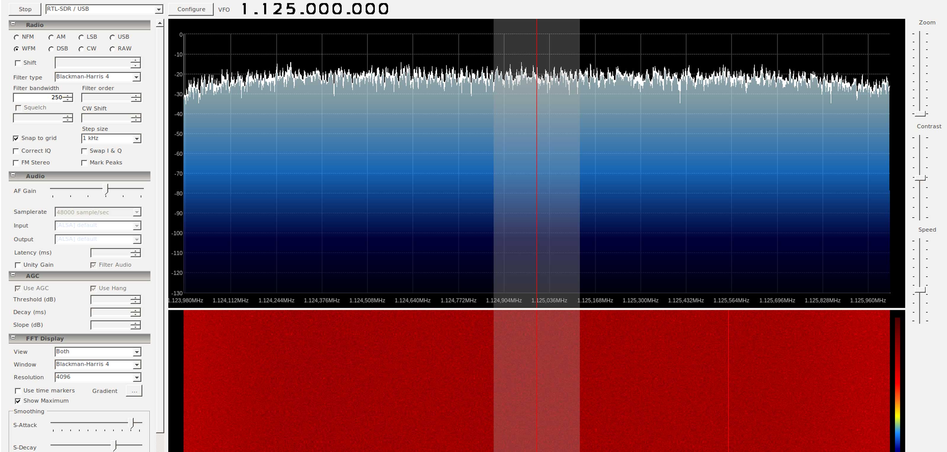
You can start the SDR#, select the receiver and view/hear the noise:
Continuously check
The first simple check can be done using rtl_test that reads the samples from the single channel receivers and reports if any samples were lost during the transmission. You have to start all your single channel receivers and make the continuously check for the required sample rate.
If the samples are lost then it cannot be guaranteed that the receivers remain synchronised. Please see our support section for more details regarding the continuously check.
If the fifth dongle is added and you get the error message during the data transfer, e.g. “Failed to submit transfer 3!” “Library error -5, exiting…” Then, your Kernel limits the maximum size of all buffers that libusb can allocate to 16MB by default. In order to disable the limit, you have to run the following command as root:
rtl_sdr
rtl_sdr collects the I/Q samples and writes them to a file. You can create the script that starts all dongles to parallel capture of the samples, e.g.
Please see the help section of the rtl_sdr about more details and parameters.
MATLAB and RTL-SDR
With Communications System Toolbox™ Support Package for RTL-SDR Radio, you can use MATLAB® and Simulink® to design and prototype systems that process real time wireless signals. There is also a free ebook available on the MathWorks site that helps to learn how to receive and analyze wireless signals using RTL-SDR, MATLAB, and Simulink.
The raw, captured IQ data can also be saved into file and opened in MATLAB using the standard file functions. Please see the basic introduction prepared by Dr. Aaron Scher from Oregon Institute of Technology.
Load samples in Matlab
The samples collected by rtl_sdr provided as unsigned interleaved bytes. You can use the loadFile.m function that loads the sequence of I and Q and stores them as complex matlab vector:
Calculating the cross-correlation
Matlab has the built in xcorr function that returns the cross-correlation of two discrete-time sequences, x and y. Cross-correlation measures the similarity between x and shifted (lagged) copies of y as a function of the lag. For example, the following script loads two captured files and calculated the cross-correlation of the samples every 100.000 samples.
The results can be plotted in the Matlab. Please see the support section for more information regarding the phase drift.
GNU Radio and RTL-SDR
GNU Radio is a free software development toolkit that provides signal processing blocks to implement software-defined radios and signal-processing systems. It is widely used in hobbyist, academic, and commercial environments to support both wireless communications research and real-world radio systems.
Below we provide some examples how you can use different options in order to get cross-correlated data in GNU Radio.

General Input/Output
GNU Radio supports: files incl. FIFO, Sockets, TCP/UDP and distributed messaging based on ZeroMQ. Streams need to be calculated and aligned before sending to the GNU Radio.

Direction Finding
Direction Finding (preparation)
You can use a 4-channel Entry Level Receiver for these experiments (e.g. Coherent-Receiver 4+1 RTL-SDR). The description is based on the standard clock card. CLK10 receivers based on ESP32 need comparable steps but use ESP32 GPIO for the management of the noise source and antenna switches.
- Identify all receivers and set custom serial numbers
- Tune the supervisor to the FM-Station and test that it works
- Connect the single channel receiver to the USB: you need to have connected following devices: noise generator; supervisor and single channel receiver
- https://coherent-receiver.com/support; Please take a look at the section Management of the antenna switch and noise generator cards:
- Try to switch the bias_tee on on the receiver. Bias_tee is the power supply of the antenna switch card (antenna switch does not work without power supply). You can use the existing program rtl_biast for this proposes
- ON: rtl_biast -dX -b 1
- OFF: rtl_biast -dX –b 0
- X is the number of the dongle (0, 1, 2, 3); please note; the supervisor don’t have the antenna switch but the command will work (it changes only the GPIO state)
- As a result the led “software selectable bias_tee” must be switched on/off depending on the command
- You do the same programmatically using the GPIO:
// true – bias on; false – bias off
setGPIOBit(handle, (byte) 0x01, true);
- Try to switch the bias_tee on on the receiver. Bias_tee is the power supply of the antenna switch card (antenna switch does not work without power supply). You can use the existing program rtl_biast for this proposes
- Switch the antenna switch between noise and antenna input; please see sections: “Antenna switch and noise generator card management” and “I2C and RTL2832U”
- Start a SDR program; select the supervisor – you should be able to listen FM-radio; select another receiver – you have to get noise signal
- You need to send the I2C command to the noise generator/antenna switch in order to switch from noise to antenna. You need to read the specification, understand the pseudocode below and write you own routine:
- //http://www.nxp.com/documents/data_sheet/PCA9534.pdf
- Specification
- Device Address:
- 0100 000 0 = 0x40 – Write; 0x41 – Read
- Register 3: configure as an output; 0 = corresponding pin enabled as an output
- Register 1: LED: 0 is on; 1 is off
- pins description is in the schema, e.g. 0x01 – d6 is on; all other are off
- //Enable I2C Repeater
- enableI2CRepeater(handle, true);
- //Write I2C register
- writeI2CRegister (handle, (byte) 0x40, (byte) 0x03, (byte) 0x00, false )
- //ox00 – FM; 0x1f – noise
- writeI2CRegister (handle, (byte) 0x40, (byte) 0x01, (byte) 0x00, true )
- The result should be: the led indicator (switch state) on the antenna switch will be on/off and you have to hear the FM radio instead of noise. Please note: you should to send the I2C-command to the supervisor (not to the receiver!). Therefore, please choose the write handle.
- If you were successful with the previous step; please connect all receivers and switch the state for all receivers between the noise and antenna input
- You can use GNU Radio and Ettus Blocks for direction finding routines; please install GnuRadio and EttusBlocks https://github.com/EttusResearch/gr-doa
- Data synchronisation
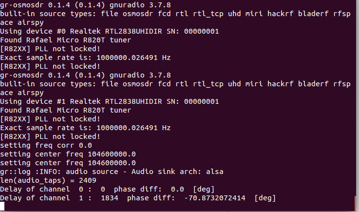
- In order to align the data, you need to calculate the cross-correlation function; please read the sources in Internet or links in the getting started section but you will need to do something like this:
- //– FFT A — –;
- fft.complexForward(a);
- //– FFT B — –;
- fft.complexForward(b);
- // — Conjugate B — —
- CrossCorrFFT.conjugate (b);
- // Element-wise multiplication
- float[] c = CrossCorrFFT.elemwiseMult(a,b);
- // — IFFT — –;
- fft.complexInverse(c, true);
- Complex max = CrossCorrFFT.getMax(c);
- You can visualize the result in GNURadio in order to see the typical cross-correlation peak
- You can do all this steps in the GNURadio using block; please check it itself
- Please note; that you need to calculate the cross-correlation function and find maximum by switched noise-on;
- Next step is to send the intervealed aligned IQ-data to GNURadio. You can do it via TCP, FileSource or ZMQ. ZMQ is most preferred option.
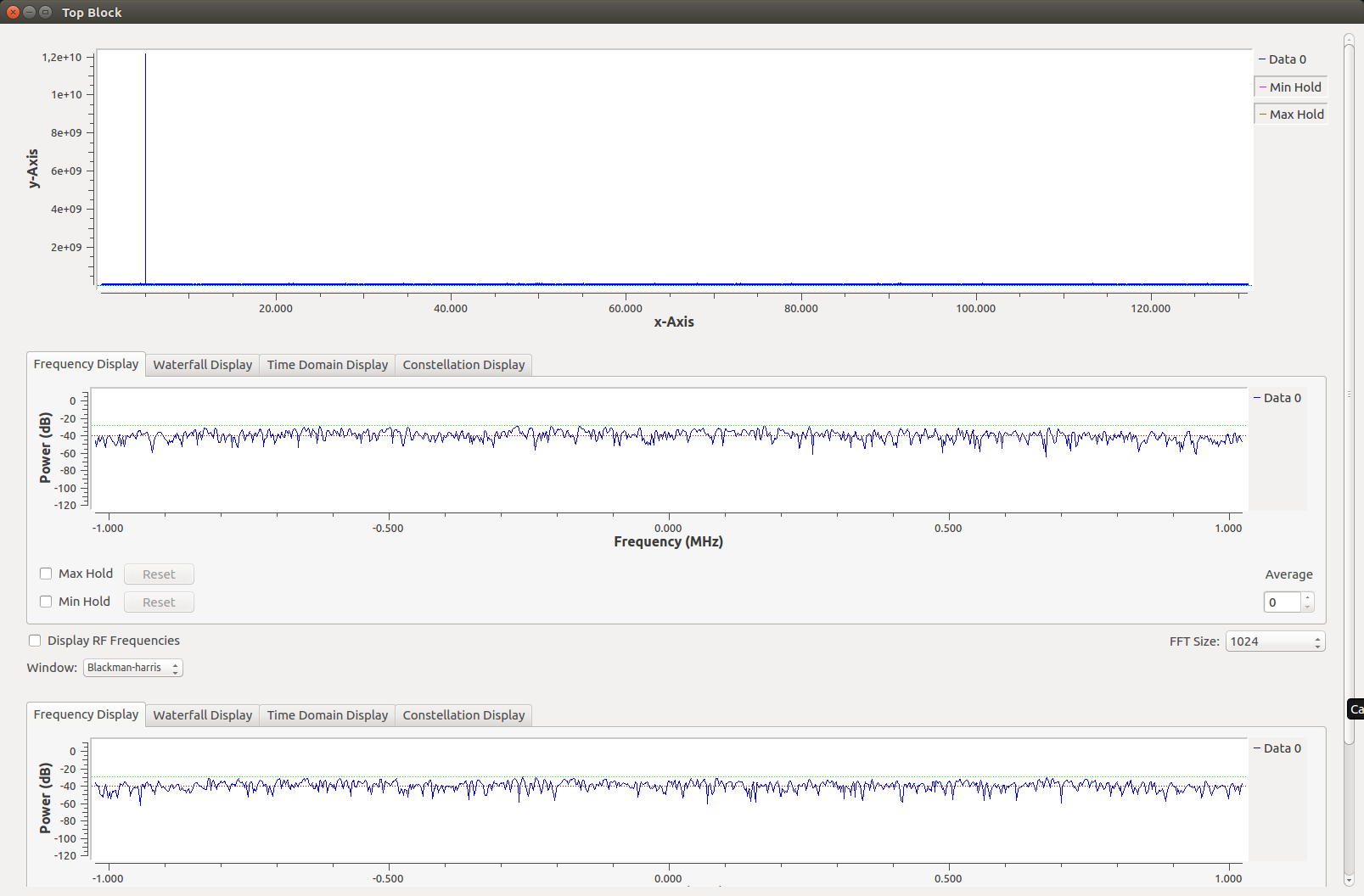
- Please create the following diagram in GNU Radio: https://coherent-receiver.com/wp-content/uploads/2017/09/ExternalCorrelation-2.png
- You can start gnuradio and have to see something like this:
https://coherent-receiver.com/wp-content/uploads/2016/09/music2.png - The next steps will be: install properly 4 antennas and provide the direction finding signal. Please do all cross-correlation and alignment on the same frequency as the DF-signal-source.
Direction Finding (easy version)
You can use a 4-channel Entry Level Receiver for these experiments (e.g. https://coherent-receiver.com/wp-content/uploads/2018/02/DirectionFindingSystem.jpg). You will need only 2 channels and a supervisor for this experiment. Moreover, you have to install two antennas spaced 1/2 wavelength apart. You can use an ordinary walkie-talkie as a signal source.
This example is based on the gnuradio-doa blocks. Please take a look at the presentation from Sam Whiting explaining gnuradio flowgraphs and OOT modules for DOA analysis and phase synchronisation before you start.
The necessary steps are:
- Identify all receivers and set custom serial numbers
- Connect antenna and tune the supervisor to the local FM-Station and test that it works
- https://coherent-receiver.com/support; Please take a look at the section Management of the antenna switch and noise generator cards:
- Enable the bias_tee on all receivers with antenna switches. Bias_tee is the power supply of the antenna switch card (antenna switch does not work without power supply). You can use the existing program rtl_biast for this proposes
- ON: rtl_biast -dX -b 1
- OFF: rtl_biast -dX –b 0
- X is the number of the dongle (0, 1, 2, 3); please note; the supervisor don’t have the antenna switch but the command will work (it changes only the GPIO state)
- As a result the led “software selectable bias_tee” must be switched on/off depending on the command
- You do the same programmatically using the GPIO:
// true – bias on; false – bias off
setGPIOBit(handle, (byte) 0x01, true);
- Enable the bias_tee on all receivers with antenna switches. Bias_tee is the power supply of the antenna switch card (antenna switch does not work without power supply). You can use the existing program rtl_biast for this proposes
- Switch the antenna switch between noise and antenna input; please see sections: “Antenna switch and noise generator card management” and “I2C and RTL2832U”
- Start a SDR program; select the supervisor – you should be able to listen FM-radio; select another receiver – you have to get noise signal
- You can use the above mentioned program rtl_biast for the supervisor management
- rtl_biast -d 2 -a 0x40 -v 0x00 //RF input
- rtl_biast -d 2 -a 0x40 -v 0x1f //Noise input or Input from noise expansion
- The result should be: the led indicator (switch state) on the antenna switch will be on/off and you have to hear the FM radio instead of noise. Please note: you should to send the I2C-command to the supervisor (not to the receiver!). Therefore, please choose the write handle.
- If you were successful with the previous step; please connect all receivers and switch the state for all receivers between the noise and antenna input to the noise state
- You can use GNU Radio and gnuradio-doa blocks from Sam Whiting for direction finding routines; you have to set the dithering_off in case of R820T2. You can do it as follows:
  ret = rtlsdr_set_dithering(_dev, 0);

if (ret) {

fprintf(stderr, "dithering off - failure\n");

} else {

fprintf(stderr, "dithering off - success\n");

}
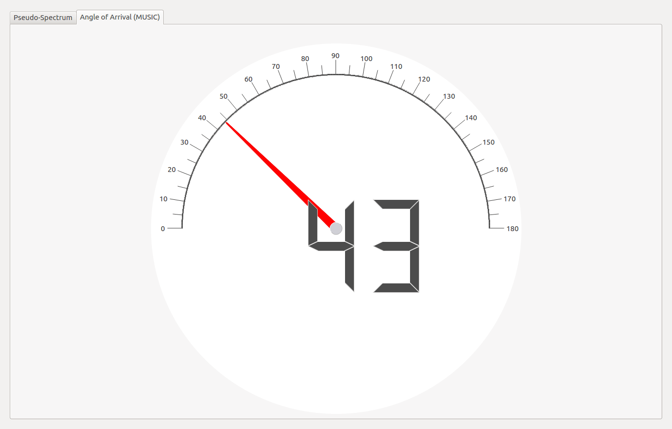
- The simplest DOA realisation is based on 2 channels: min_coh_2. This example includes cross-correlation and DoA-routines. Therefore, you just need to start it and after cross-correlation set the antenna switches to the RF-input using the rtl_biast. There are several tutorials that describes all details of PCA incl. math (eigenvalue and eigenvector, covariance matrix etc.).

Walkie-talkie is turned off

Walkie-talkie is turned on

Python and RTL-SDR
Python is very well suited for rapid prototyping. Compared to MatLab, all functionalities do not ship with Python. But the language has a huge selection of libraries (batteries included), e.g. for linear algebra so that developed algorithms can be tested on real data. We added necessary functionalities to the standard Python wrapper (pyrtlsdr) in order to support coherent receiver hardware. The modified python wrapper can be found on github. Please note that you have to use our custom modification of the Keenerd rtl-sdr library. Python wrapper includes several examples based on the synchronous or native Python 3 asynchronous modes:
Initialisation:
Samples reading
Cross-correlation
Cross-correlation calculation can be done as follows:
Send to consumer
We recommend to use ZeroMQ for the inegration with GNU Radio and provide the aligned and phased corrected interleaved samples: